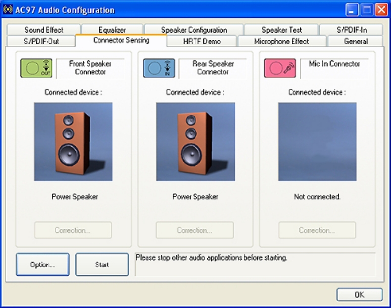

Dell manuals describe it as front audio (F_AUDIO) and don't indicate any such jumper, and only describe the BIOS option Onboard Audio Controller as Enabled or Disabled (Enabled by default).
AC 97 AUDIO MANUAL
My own motherboard (MSI P67A-C45) manual just says it's compliant with the Intel Front Panel I/O Connectivity Design Guide, not all that much information. It is recommended that you look at your motherboard manual. Some sources indicate that it is/may be necessary to switch audio output modes in the BIOS configuration or with a jumper. Should note that AC’97 and Intel High Definition Audio front panel motherboards and I/O cards implementations are different and may not be directly compatible or interchangeable Motherboard designs are switching over to High Definition (HD) audio CODECs. With the introduction of Intel High Definition Audio, many new In the past, AC’97 Integrated Audio CODECs were prevalent. I will be adding emphasis.įront panel audio design in conjunction with motherboard audio header design is dependant upon the type of audio CODEC being used on the motherboard. They also have schematics on pages 20 and 25 if you care. The rest of this answer will be referencing the Intel Front Panel I/O Connectivity Design Guide, page 19. For average home use, there shouldn't really be a noticeable difference. The linked articles have more detail on that. The matching connector on your case should be labelled accordingly, I know mine is labelled HD Audio. While the connectors may look identical, the pinouts are different and not really interchangeable. Those cables are typically used to connect front panel headphone/microphone ports. The VHDL system hierarchy can be seen in the RTL diagram in Figure 1 below.The correct one to use depends on your case.

This process in the top level file can be replaced by port mapping user components for various signal processing tasks. This makes the ac97 talk through from input to output. The top of the hierarchy simply routes the parallel outputs of the controller to back into the parallel inputs of the controller on clock edges.
AC 97 AUDIO DRIVER
The two parts of the ac97 hardware driver are synced with a one cycle, pulsed ready signal. The FSM can be changed to include user bus signal inputs, routed to each state corresponding to different register values, for on the fly configuration of the codec.
AC 97 AUDIO SERIAL
The controller has two main parts, the ac97 for generating signals, and converting 18 bit parallel data to serial data to interface the ac97 chip with the FPGA, and the command controller state machine used to configure the registers in the ac97 in a round robin fashion. Consult the LM4550 data sheet for details on the serial frame input/output. One of these signals pulses every 20us and the other is a signal used for error checking during the tag phase. There are two internal signals to sync the main ac’97 controller with the command state machine. The controller’s outputs include a sync signal, serial data output, and an ac97 active low reset signal for initializing the ac97. The inputs to the controller include the main FPGA oscillator, an active low reset, a serial data in line, a 12.288 MHz bit clock from the ac’97 chip, a 3 bit source selector (slide switches) and a 5 bit volume control (slide switches).

The data sheet for the LM4550 ac’97 codec can be found below: A Spartan 6 FPGA was used to develop the ac’97 controller, but any FPGA can be used as long as the signal timing is taken into consideration with respect to the main system clock. The design can be scaled to other clock speeds by either scaling the internal counters, or instantiating an onboard PLL to attain a 100 MHz clock. This is an example hardware driver used to interface a National Semiconductor LM4550 ac97 audio codec with an FPGA running at 100 MHz.


 0 kommentar(er)
